MCC PANEL – A Motor Control Center (MCC) is an assembly to control some or all electric motors in a central location. A motor control center can also include more switch gears, a lot of switchgears like this.
MCCB
MCCB - Molded Case Circuit Breaker or MCCB is low voltage switch-gear which protects electrical devices from short circuit and overloads. Simply, MCB is used for current rating from 0.5–125A where as for higher ratings MCCB is used. (16- 1250A) MCCB is also available specifically for Motor protection. It stands for Molded Case Circuit Breaker and the main feature is that the current setting is adjustable in these kind of circuit breakers.
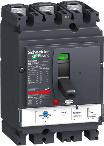
SPREADER LINK
SPREADER LINK - A mechanical device for scattering something in all directions, a hand tool for spreading something.
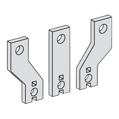
MCB ISOLATOR
MCB ISOLATOR - Isolator Switches are designed to isolate an electrical circuit from its power source. It is a switching/isolation device, intended to disconnect an electrical equipment or electrical Load from the supply. It is an offload device, it can be operated only when the current passing through the circuit is zero. It can be operated only during offload condition. The basic intention behind of using an isolator is to ensure safety during maintenance. Before operating an isolator it must be ensured that the current flowing through the circuit is zero or within safety limits.
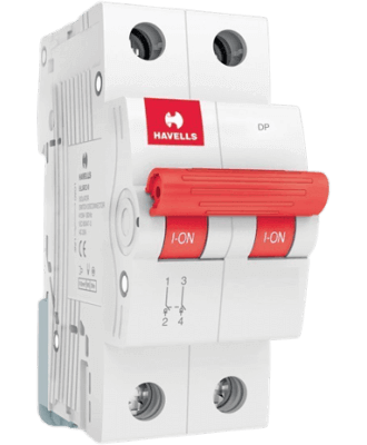
MCB
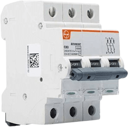
MCB – Miniature Circuit Breaker is low voltage switch-gear which protects electrical devices from short circuit and overloads. Simply, MCB is used for current rating from 0.5–125A where as for higher ratings MCCB is used. (16- 1250A) MCCB is also available specifically for Motor protection. It stands for Miniature Circuit Breaker and the main feature is that the current setting is not adjustable in these kind of circuit breakers.
A miniature circuit breaker (MCB) automatically switches off electrical circuit during an abnormal condition of the network means in overload condition as well as faulty condition. We use an MCB in low voltage electrical network instead of a fuse. The fuse may not sense it but the miniature circuit breaker does it in a more reliable way. MCB is much more sensitive to over current than fuse. MCB is electrically safer than a fuse. Quick restoration of supply is possible in case of a fuse as because fuses must be re-wirable or replaced for restoring the supply. Restoration is easily possible by just switching it ON. Whenever continuous overcurrent flows through MCB, the bimetallic strip is heated and deflects by bending. This deflection of bimetallic strip releases a mechanical latch. As this mechanical latch is attached with the operating mechanism, it causes to open the miniature circuit breaker contacts, and the MCB turns off thereby stopping the current to flow in the circuit. To restart the flow of current the MCB must be manually turned ON. This mechanism protects from the faults arising due to over current or overload. But during short circuit condition, the current rises suddenly, causing electromechanical displacement of plunger associated with a tripping coil or solenoid. The plunger strikes the trip lever causing immediate release of latch mechanism consequently open the circuit breaker contacts. This was a simple explanation of a miniature circuit breaker working principle. An MCB is very simple, easy to use and is not generally repaired. It is just easier to replace. The trip unit is the main part, responsible for its proper working. There are two main types of trip mechanism. A bi-metal provides protection against overload current and an electromagnet provides protection against short-circuit current.
MPCB
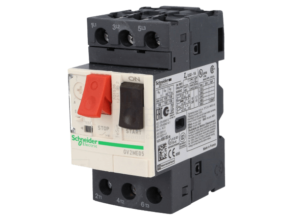
MPCB – Motor Protection Circuit Breakers and are devices used to open and close a circuit manually and interrupt the circuit automatically on the occurrence of faults & used to manually turn on and off electric motors and at the same time protect them from different types of faults occurring in motors. Motor Protection circuit Breaker can protect motors against overload, short circuits, phase loss and under-voltage faults. Motor Protection Circuit Breaker are specially designed for motor protection. Maximum load current can be set based on the full load current of the motor.
Motor Protection Circuit Breaker are selected based on the full load current of motors and maximum possible short circuit current. Motor Protection circuit Breaker can withstand the starting currents without interrupting the circuit. Motor Protection Circuit Breaker have an adjustable bimetallic strip for overload protection. This strip can be adjusted between two set values. Overload relay is not required for motor circuits with Motor Protection circuit Breaker backup. A Motor can be directly turned ON and OFF manually using a Motor Protection circuit Breaker a contactor is optional. Some Motor Protection Circuit Breaker come with an auto-resetting feature which allows motors to resume its operation after a short period from the occurrence of overload trip.
Why Are Use MPCB?
Why Are Use MPCB – Motors draw a very high pressing current during startup, because they must establish a rotating magnetic field. This current can reach values of 400% to 700% of the rated value for a few part of a second. For this reason, the MPCB magnetic protection trips at values greater than 10 times the rated current incase of miniature circuit breakers which trip at values as low as 3 times rated current. In order to reduce the inrush current, a very common practice is to complement the motor protection circuit breaker with a reduced voltage motor starter.
Motors require the three phase conductors to have a balanced voltage in order to operate properly. If the phase conductors have an unbalance greater than 2%, the motor will suffer damage over time and will have a reduced service life. The electric motor will also tend to overheat, causing additional energy expenses as waste heat. For this reason, a Motor Circuit Breaker must be able to detect phase imbalance and disconnect the motor accordingly.
If one of the phases is disconnected completely, the motor will keep operating but the current in the remaining two phases will rise/increases above the rated value due to the electrical unbalance, and will probably burn the motor’s windings. For this reason, motor protectors must trip immediately as soon as phase unbalance or phase loss is detected.
Contactor
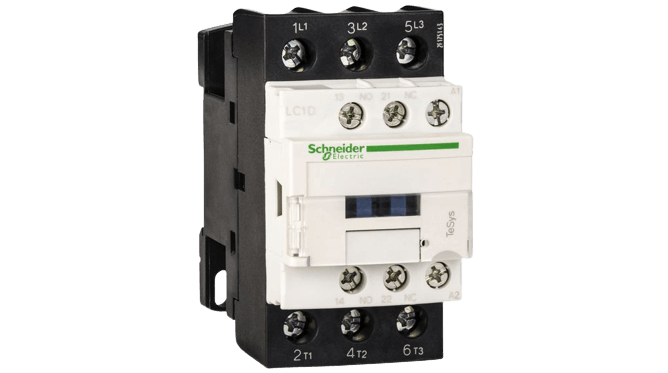
A contactor is an electrically-controlled switch used for switching an electrical power circuit. A contactor is typically controlled by a circuit which has a one circuit to other circuit. A contactor has three components. The contacts are the current carrying part of the contactor. This includes power contacts, auxiliary contacts, and contact springs.
The working principle of a contactor is like a relay, in a contactor there are several electromagnetic-controlled switches.
In a contactor there are several switches with type NO (Normally Open) and NC (Normally Close) and a coil or electromagnetic coil to control the switch.
If the electromagnetic coil of the contactor is given an AC voltage source, the switch on the contactor will be connected, or change its condition, the original FF becomes ON and vice versa which initially ON becomes OFF.
OVERLOAD RELAY
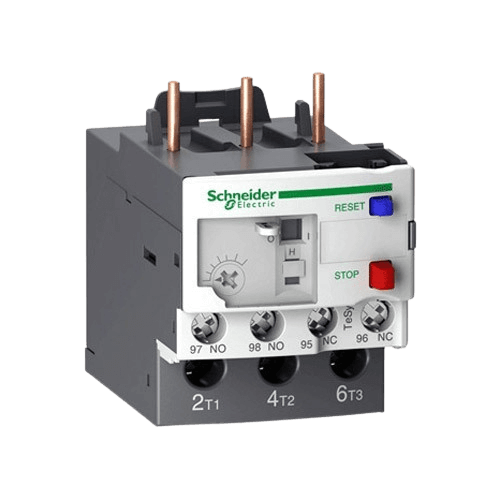
OVERLOAD RELAY - Overload relay is device that protects a motor from damages caused due to Over Loads, Over Currents, Phase Failure, Overheating and phase imbalance OF Motor winding. Overload Relay, Tripping time is always inversely proportional to the current flow through the overload relay.
Types of overload relay -
Overload Relay Can be Classified as Follows.
- Bimetallic thermal overload relay
- Electronic overload relay
Electronic overload relays do not have a bimetallic strip inside. it uses temperature sensors or current transformers to sense the total current flowing to the motor.
Protection Relay
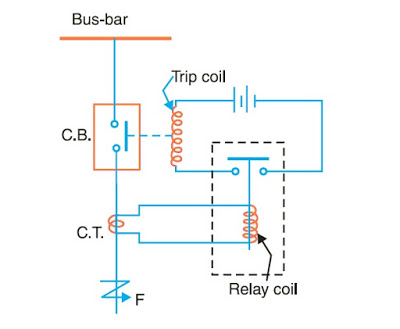
PROTECTION RELAY – Protection Relay is automatic device which senses an abnormal condition of electrical circuit and change the auxiliary contacts or NO to NC and NC to NO contacts.
Thermister Protection Relay
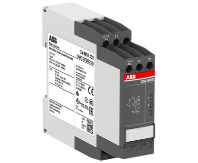
THERMISTER PROTECTION RELAY – Thermister Motor Protection Relay, Motor Winding Tempreature protects from Overheat, Overload and Insuffient cooling.
Pump Protection Relay
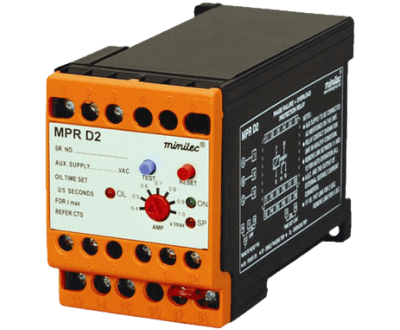
PUMP PROTECTION RELAY – Pump protects from maximum current, minimum power factor, phase loss and phase sequence.987
Overcurrent Relay
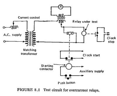
OVERCURRENT RELAY – An Overcurrent Relay is a type of protective relay which operates when the load current exceeds a pickup value. It is of two types: instantaneous over current (IOC) relay anddefinite time overcurrent (DTOC) relay.
Over Voltage Relay
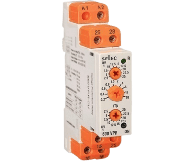
OVER VOLTAGE RELAY – An Over VOLTAGE Relay is a type of protective relay which operates when the VOLTAGE exceeds a pickup value.
Single Phase Preventer
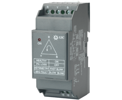
OVER VOLTAGE RELAY – Single Phase Preventer as a protection relay whitch is protects from Unsquense Phase, Phase Loss, Low Voltage and High Voltage in the Electrical System.
Water Level Controller
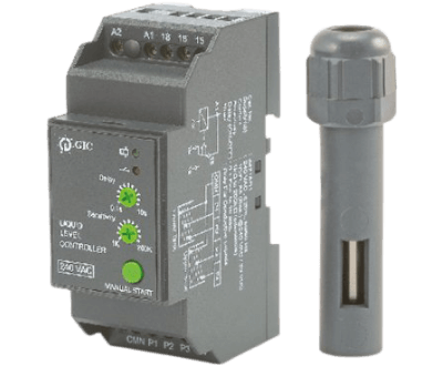
WATER LEVEL CONTROLLER – Water Level Controller (WLC) is used to control water level (up and down).
Temprature Controller
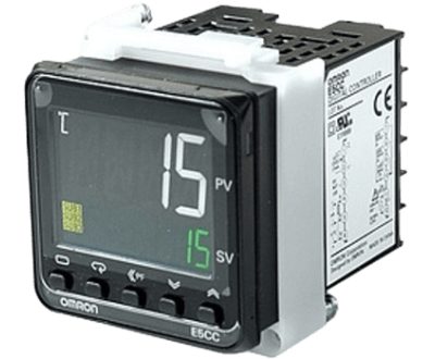
TEMPRATURE CONTROLLER – Temprature Controller is an device that is used to control temprature in process.
Hour Meter
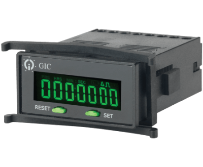
HOUR METER – An Hour Meter is a gauge or instrument that tracks and records TRANSPIRE time.
Counter

COUNTER – a counter is a device which stores the number of times a particular event or process has occurred, often in relationship to a clock.
Annunciator

ANNUNCIATOR – MOTOR, BLOWER, HEATER, Bell, Light, or other device that provides information on the state or condition of something by indicating which of several electric circuits has been activated.
Push Button

PUSH BUTTON – Push Button as a switch an control a machine or some type of process.
Push Button Element
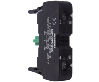
PUSH BUTTON ELEMENT – Push Button element that connects & disconnects supply two points in a circuits when you press it. These are two type NO (Normally Open) and NC (Normally Closed).
Indication Light
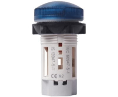
INDICATION LIGHT – Indicator is showing the operating condition of system.
Ampere Meter
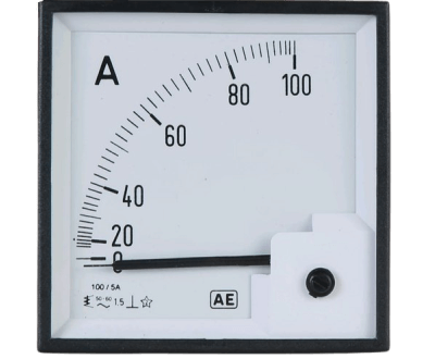
AMPERE METER – Ampere Meter is a measuring instrument used to measure the current in the circuit.
Volt Meter
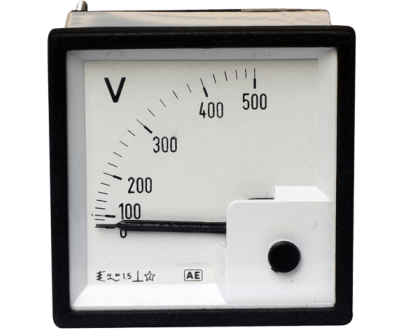
VOLT METER – Volt Meter is a measuring instrument used to measure the voltage in the circuit.
Ampere Selector Switch

AMPERE SELECTOR SWITCH – Ampere Selector Switch is a simple three position switch reduce number of ampere meter used to monitor line current.
Voltage Selector Switch

VOLTAGE SELECTOR SWITCH – Voltage Selector Switch is a simple three position switch reduce number of volt meter used to monitor line – line & line – neutral voltage.
Auto/manual Selector Switch

AUTO/MANUAL SELECTOR SWITCH – Auto/Manual Selector Switch is single pole double thow switch with a center position off.
CT (CURRENT TRANSFORMER)
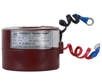
CT (CURRENT TRANSFORMER) – Current Transformer is a instument transformer that is designed to produce alternating current in the secondary winding witch is proportional to alternating current in the primary winding.
CONTROL TRANSFORMER
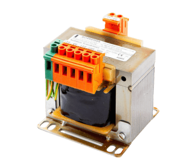
CONTROL TRANSFORMER – Control Transformer is an isolation transformer that provide good voltage stability in the secondary winding during overload condition or pressure current in system.
